|
|
- # XD84
-
- Development docs covering the following:
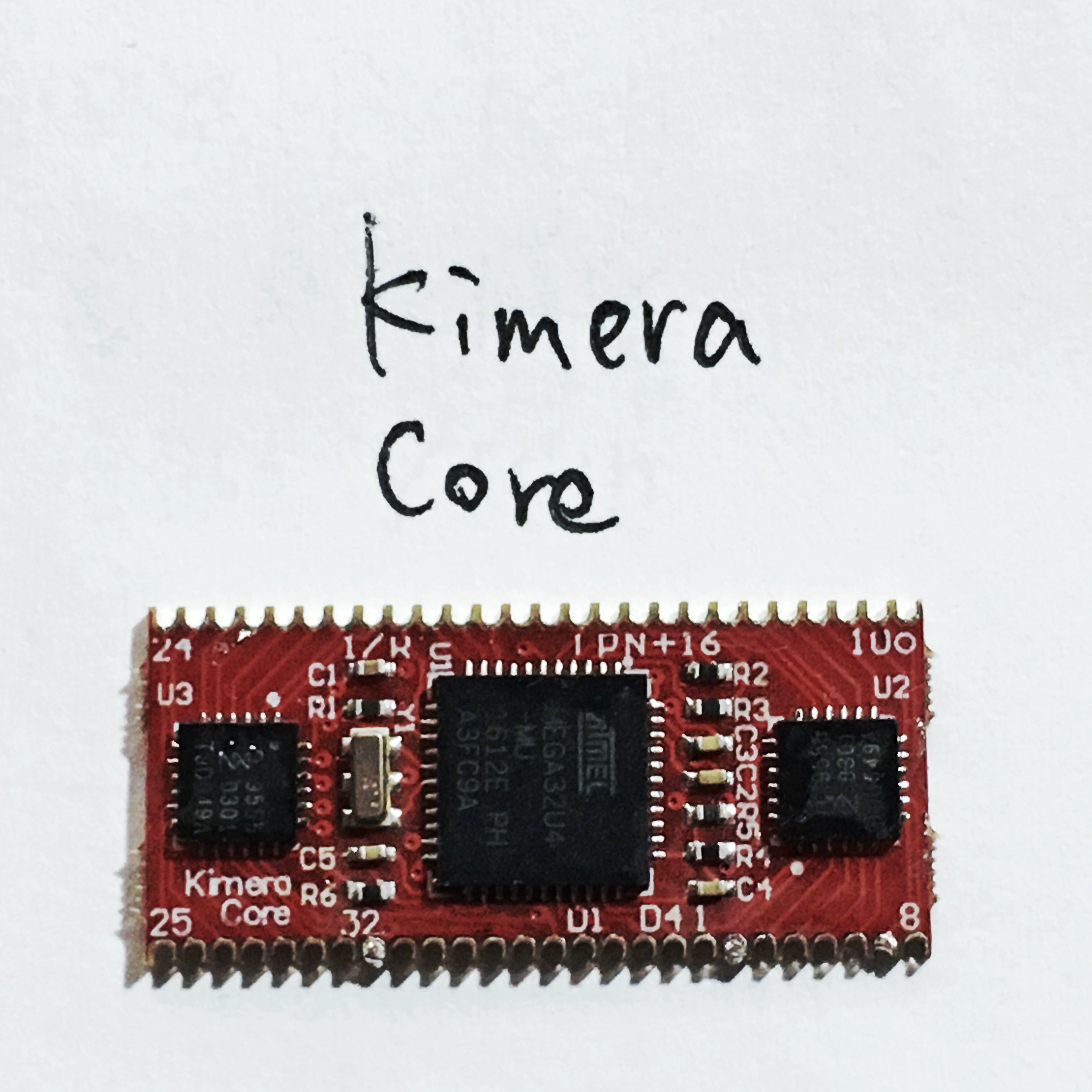
- - Kimera core
- - RGB
- - Backlight
- - Light Through Cat
-
- ## Kimera core
- 
-
- What little available info that was available for the qmk port
- - atmega32u4 16Mhz
- - board seems to have a 6Mhz crystal
- - 2x PCA9555 I2C IO expander
-
- Links:
- - [Schematic, BOM, Gerbers](/kairyu/kimera/blob/master/kimera_core)
- - [Original firmware](https://github.com/kairyu/tmk_keyboard_custom/tree/master/keyboard/kimera)
-
- ```c
- /*
- Kimera_core_v1.0 Components
-
- U1 (atmega32u4)
- ,----------------.
- TX --| TX0(PD3) RAW |--
- RX --| RX1(PD2) GND |--
- --| GND RESET |-- RST
- --| GND VCC |--
- SDA --| 2(PD1) (PF4)A3 |--
- SCL --| 3(PD0) (PF5)A2 |--
- (INT) --| 4(PD4) (PF6)A1 |--
- --| 5(PC6) (PF7)A0 |--
- --| 6(PD7) (PB1)15 |-- SCK
- LED2 --| 7(PE6) (PB3)14 |-- MISO
- LED1 --| 8(PB4) (PB2)16 |-- MOSI
- LED3 --| 9(PB5) (PB6)10 |-- LED4
- `----------------'
-
- IC1 (PCA9555) IC2 (PCA9555)
- ,----------. ,----------.
- SDA --| SDA P00 |-- P1 SDA --| SDA P00 |-- P17
- SCL --| SCL P01 |-- P2 SCL --| SCL P01 |-- P18
- INT --| INT P02 |-- P3 INT --| INT P02 |-- P19
- | P03 |-- P4 | P03 |-- P20
- GND --| A0 P04 |-- P5 VCC --| A0 P04 |-- P21
- SJ1 --| A1 P05 |-- P6 SJ1 --| A1 P05 |-- P22
- SJ2 --| A2 P06 |-- P7 SJ2 --| A2 P06 |-- P23
- | P07 |-- P8 | P07 |-- P24
- | | | |
- | P10 |-- P9 | P10 |-- P25
- | P11 |-- P10 | P11 |-- P26
- | P12 |-- P11 | P12 |-- P27
- | P13 |-- P12 | P13 |-- P28
- | P14 |-- P13 | P14 |-- P29
- | P15 |-- P14 | P15 |-- P30
- | P16 |-- P15 | P16 |-- P31
- | P17 |-- P16 | P17 |-- P32
- `----------' `----------'
- */
-
- ```
-
- ### Bootloader
- Default bootloader is `atmel-dfu`.
- Reboot to bootloader via magnetic switch next to icsp header.
- Flash using regular dfu methods.
-
- ### XD84 pin mappings
- Taken from [kimera-config.json](https://github.com/kairyu/tkg/blob/master/keyboard/config/kimera-config.json)
-
- "row_mapping": [ 1, 2, 3, 4, 5, 6 ],
- "col_mapping": [ 17, 18, 19, 20, 21, 22, 23, 24, 25, 26, 27, 28, 29, 30, 31 ],
-
- # RGB
- - PIN C7
- - Number of RGB LED 7
-
- # Backlight
- - PIN B6
-
- # Light Through Cat
- TODO - PWM C6
-
- ## Assumptions
- ### Pin/Port mappings
- - All cols are on the same IC
- - All rows are on the same IC and port
- - Pins mapped sequentially
- - Each port only does row or column not a mixture of both
- - No need to have complex port config
- -
-
- | ROW index | Kimera Pin | PCA9555 |
- | ----------|------------|-------------------|
- | 0 | 1 | IC1 Port 0 pin 0 |
- | 1 | 2 | IC1 Port 0 pin 1 |
- | 2 | 3 | IC1 Port 0 pin 2 |
- | 3 | 4 | IC1 Port 0 pin 3 |
- | 4 | 5 | IC1 Port 0 pin 4 |
- | 5 | 6 | IC1 Port 0 pin 5 |
-
- - Safe enough to assume `row_index == pin`
-
-
- | COL index | Kimera Pin | PCA9555 |
- | ----------|------------|-------------------|
- | 0 | 17 | IC2 Port 0 pin 0 |
- | 1 | 18 | IC2 Port 0 pin 1 |
- | 2 | 19 | IC2 Port 0 pin 2 |
- | 3 | 20 | IC2 Port 0 pin 3 |
- | 4 | 21 | IC2 Port 0 pin 4 |
- | 5 | 22 | IC2 Port 0 pin 5 |
- | 6 | 23 | IC2 Port 0 pin 6 |
- | 7 | 24 | IC2 Port 0 pin 7 |
- | 8 | 25 | IC2 Port 1 pin 0 |
- | 9 | 26 | IC2 Port 1 pin 1 |
- | 10 | 27 | IC2 Port 1 pin 2 |
- | 11 | 28 | IC2 Port 1 pin 3 |
- | 12 | 29 | IC2 Port 1 pin 4 |
- | 13 | 30 | IC2 Port 1 pin 5 |
- | 14 | 31 | IC2 Port 1 pin 6 |
-
- - Safe enough to assume here col_index does not need to be converted to pin
- - Reading both ports one after the other gives us the same sequential behavior
- - maps to the usual practice of reading matrix columns
- - while this technically gives 16 column reads, the 16th column can never be set so is safely ignored
-
- ## Notes
- [pca9555 datasheet](https://www.ti.com/lit/ds/symlink/pca9555.pdf)
-
- - Other Kimera based boards with non sequential pin mappings, pins mapped across ICs, or mixed row/col configs will need more complicated `pin -> i2c_addr,port,pin` logic as well as rather more complex pin functions.
-
- ## Return to stock firmware
- Not tested but original firmware seems to be available in the [kairyu/tkg-firmware](https://github.com/kairyu/tkg-firmware/blob/master/kimera-core.hex) repo.
|

